Can you please answer our following questions :
1°) In the configuration GigaBlox Nano 1-inch Gigabit Ethenet switch board + Nano RJCon board, we see that each board includes a power supply connector as follows :
So, our question is: do we need to supply both boards? can you clarify and be precise on which connector we must put the power supply (and confirm we can use a +5VDC power supply).
2°) How can we use the Nano with an upstream link of 10 meters long? Please confirm this will work with the add-on RJ-45 connectors card (BB-GNR-A-1). And with the BB-GNP-A-1? (If we understand well, the max IP link is less than 1 m) :
3°) Please clarify this :
Thanks for your questions. Please see our clarifications below.
1) Powering GigaBlox Nano + RJConn / PicoConn
Each daughterboard is designed to be used with its own GigaBlox Nano — they are not mixed.
-
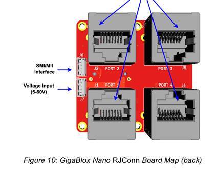
RJConn stack: Mate GigaBlox Nano RJConn (BB-GNR-A-1) with a GigaBlox Nano board. Apply power only via the J7 Molex PicoBlade connector.
-
PicoConn stack: Mate GigaBlox Nano PicoConn (BB-GNP-A-1) with a GigaBlox Nano board. Apply power only via the J6 Molex PicoBlade connector.
-
The datasheet specifies 5.1 V to 60 V DC input range. In practice, a regulated +5 V supply is fine as long as it does not fall below 4.5 V under load.
 Important: Do not connect power to both the Nano and the daughterboard separately. Always power the stack through the daughterboard’s designated connector. Connecting to the wrong header (J6 vs J7) can permanently damage the board.
2) Using a 10 m upstream link
-
RJConn: This daughterboard includes RJ-45 connectors with integrated transformers, making it IEEE 802.3-compliant. A 10 m Cat5e/Cat6 cable is well within specification and should work as expected.
-
PicoConn: This board is transformerless (capacitive coupling only). For reliable operation, transformerless Ethernet should be limited to ≤ 1 m cables with all devices sharing a common ground, and PoE must not be used. A 10 m link is very unlikely to work on PicoConn, as such lengths typically require transformers to maintain signal balance.
3) Clarification of the “cabling topology” text
The datasheet section means:
-
A GigaBlox Nano in transformerless mode (e.g. with PicoConn) can safely connect to a PHY that uses transformers (i.e. a standard Ethernet port with magnetics). This works because the isolation is provided on the PHY side.
-
A GigaBlox Nano in transformerless mode can also connect to another transformerless PHY, provided both use capacitive isolation and share the same ground.
In short:
-
Transformerless → Transformer-based PHY: valid.
-
Transformerless → Transformerless PHY: valid, but only if devices share ground and the cable is ≤ 1 m.
-
Transformerless → Transformerless at long distance / different grounds: not valid.
(Reference: GigaBlox Nano Datasheet, Transformerless Ethernet section, cabling topology note.)
 Summary:
-
Each stack is powered through its daughterboard only: RJConn → J7, PicoConn → J6.
-
Input voltage: datasheet says 5.1–60 V, but in practice 5 V is fine provided it does not dip below 4.5 V.
-
10 m upstream link works with RJConn, but not with PicoConn.
-
The “cabling topology” note means PicoConn (transformerless) can connect either to a standard PHY (transformer-based) or to another transformerless PHY, provided the ground and cable constraints are met.