– Copied from customer email –
We are currently developing an industrial grade scanner with 3 cameras that need to be connected to a small computer.
The computer has one 2.5 Gb ethernet port. The camera configuration is as follows:
- Cameras 1 and 2:
- Camera 3:
- 1000BASE-T1, Automotive ethernet
I wanted to see if I can use the SPEBlox in conjunction with the Gigabit Switch rugged, to hook the 3 cameras to the single 2.5 Gb ethernet port on the computer.
Also, are the Ethernet connections on the Gigabit Switch capable of PoE? I have put the details of the voltage required in the attached PNG.
I have attached a PNG showing how I would like to wire the 3 cameras using the SPEBlox and the GigaBit Switch.
Yes you can use SPEBlox in conjunction with GigaBlox Rugged as in your diagram. You would need an 8-way picoblade to picoblade cable, which is included with SPEBlox.
GigaBlox Rugged does not have POE capability onboard, but you can add a PoE injector between GigaBlox Rugged and your cameras to achieve this.
You could also look at using POEBlox for the POE, but that is not due for release until March 2024.
Also please note that the 2.5G ethernet port on the PC will only run at 1G maximum. Also bear in mind that you’ll end up with a bottleneck on that port if all three cameras decide to stream at 1Gbps simultaneously.
So if I am understanding you correctly, when I connect the GigaBlox Switch to the Ethernet port on the computer, I will effectively make the max speed of the 2.5G port to 1G. And since I have 3 cameras connected, and if they are streaming at full load, then the total load on the port is 3Gbps but the port will only be capable of handling 1Gbps. Is this correct?
Could you give me your feedback on the systems below?
System 1:
- Does not use PoE
- Cameras 1 and 2 connected to the First 2.5G ethernet, I am assuming this will still create a bottleneck if both cameras run at 1Gbps
- Camera 3 connected to a separate Second 2.5 ethernet port, will this port only run at 1G maximum?
- Camera 3 also powered using the SPE PoE
System 2:
- Uses the PoEBlox card for PoE
- Cameras 1 and 2 connected to the First 2.5G ethernet, I am assuming this will still create a bottleneck if both cameras run at 1Gbps
- Camera 3 connected to a separate Second 2.5 ethernet port, will this port only run at 1G maximum?
- Camera 3 also powered using the SPE PoE
So if I am understanding you correctly, when I connect the GigaBlox Switch to the Ethernet port on the computer, I will effectively make the max speed of the 2.5G port to 1G. And since I have 3 cameras connected, and if they are streaming at full load, then the total load on the port is 3Gbps but the port will only be capable of handling 1Gbps. Is this correct?
In ethernet, two ports will auto-negotiate the highest possible speed that both ports can achieve. This means if you connect a 2.5G port to a 1G port, the 2.5G port will set its speed to 1G so both ports can communicate. This process is called autonegotiation.
If all three cameras decide to stream at 1Gbps simultaneously into a 1Gbps port, then yes, you will have a bottleneck and lose data. It’s highly unlikely that both your cameras would be streaming that much data. For comparison, a 4K video streamed using H.264 encoding needs around 32Mbps, so unless your cameras are streaming some kind of high-def raw format, you’re not likely to see a bottleneck. Check with the camera manufacturer.
If you knew for a fact you’d be having a constant stream of 3 x 1Gbps into a single port, then you’d need to choose a speed for that port that could handle it (for example, a 5Gbps or 10Gbps could handle it).
In system 1:
- Any 2.5G port connected to a 1G port will run at 1Gbps. So all cameras will run at 1Gbps and all ports on your computer will run at 1Gbps.
- SPE PoE is not a very mature technology, there are a few ways of doing it and a lot of hardware is not unified. Our boards no longer support SPE based PoE, so you’ll need to power the camera seperately.
In system 2:
- To use POEBlox to power your device, your device must be compatible with IEEE 802.3af, IEEE 802.3at, IEEE 802.3bt (type 3) or IEEE 802.3bt (type 4). If so, then it will work.
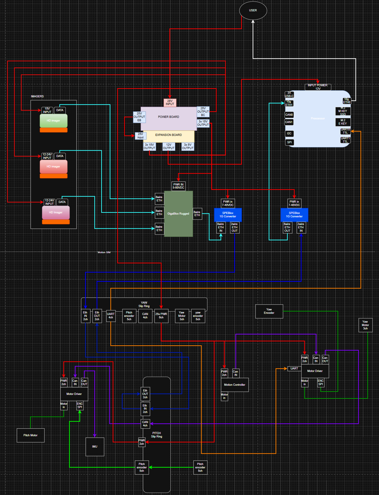
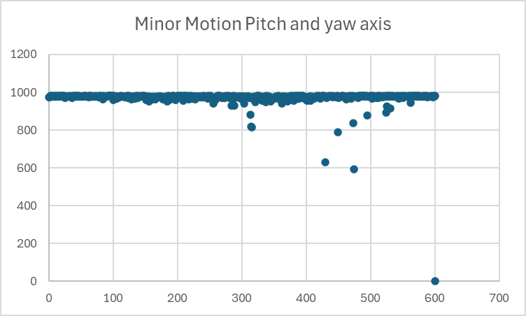
We are implementing a similar architecture, however we are including two slip rings to allow imager placement on a gimbal (Pitch & Yaw)
In this development architecture, imager are placed outside of the motion sim with SPE and power flowing through the pitch and yaw slip rings(GbE Rated) then back out to the user. We are doing this in order to stress the SPE and other signals over the sliprings.
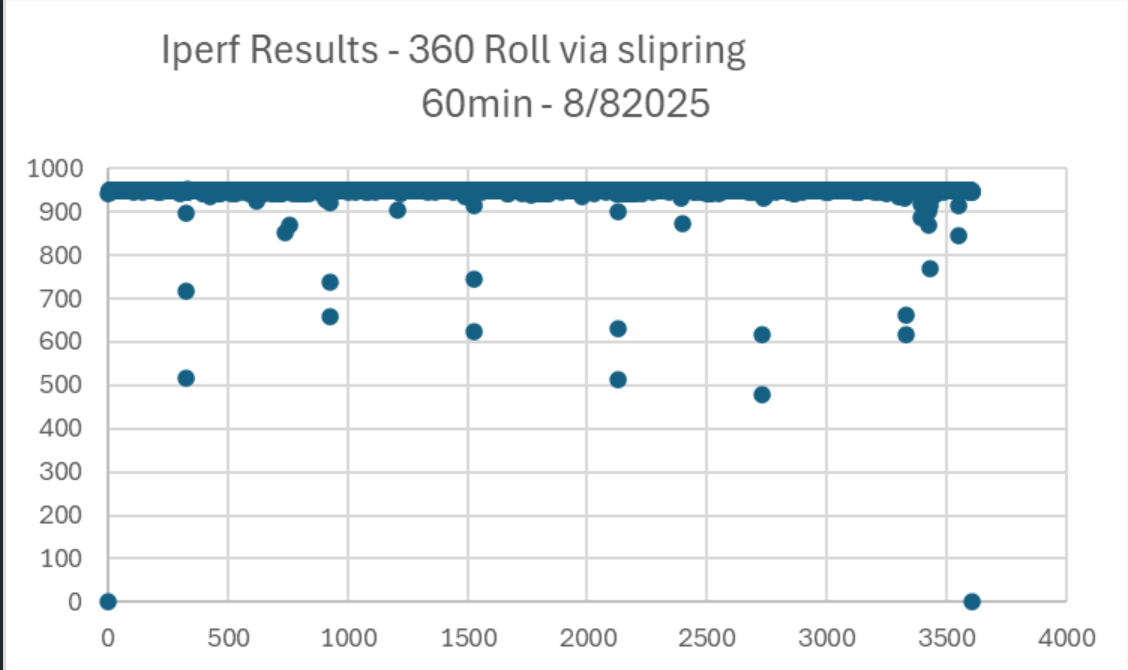
Initial testing proved good results but we are starting to see some slow bandwidths with longer duration tests.
Any suggestions for troubleshooting? Or is this expected behavior?
There’s a one thing I didn’t understand about your diagram… The SPE link goes into the slip ring then back out of the slip ring, but doesn’t connect to anything beyond the slip ring. I don’t really understand that; I’d expect the SPE link to go into the slip ring to connect to some SPE device inside the payload. Anyway this is somewhat tangential, I’m just keen to fully understand your system in case I miss any potential issues.
– Never mind, you did explain it; you’re just putting it through the slip ring like that to test the SPE connection.
There’s a lot going on here, the trick to solving this is breaking the problem down.
1. Prove it’s the slip rings
Run the same iperf test in a few configurations:
- No slip rings at all – straight cable → should be a flat line at ~940 Mb/s.
- Single slip ring, stationary
- Single slip ring, moving
- Two slip rings in series, stationary
- Two slip rings, moving
You’re looking for when the dips first appear and how bad they get.
If it’s clean until you move, that strongly points to contact noise / impedance variation with rotation rather than thermal or cabling.
2. Separate “motion” effects from “motor noise”
Run the moving tests with different combinations:
- Gimbal moving but motors unpowered / driven gently (hand-rotate if possible).
- Motors enabled, high torque / PWM, but keep the angle static.
If errors track motor current / PWM duty more than angle, you may be fighting EMI coupling inside the slip ring:
- Try to assign dedicated rings / bundle for Ethernet away from motor phases.
- Use shielded cable into and out of the slip ring, with the shield bonded 360° to chassis at least one side.
- Ensure good grounding strategy so motor return currents aren’t flowing in your Ethernet reference.
3. Look for time-related / thermal effects
Because your plot shows more “mess” later in the run, it’s worth checking:
- Repeat the test long duration but no motion, does it stay flat or slowly degrade?
- Put a temp probe on the slip ring and nearby PHYs / switch; excessive heating can shrink SNR margin.
If it degrades with time even when static, the issue might be thermal drift in the PHYs or the slip ring resistance increasing as it warms.
Is this “expected”?
Practically:
- For perfectly designed cabling + a good quality GbE slip ring, you can get a completely flat 1 Gb/s over long runs and motion.
- With two slip rings in series, lots of extra connectors, power + motors all sharing the assembly, it’s not surprising to see exactly the kind of intermittent dips you’ve plotted.
So I’d say:
- Not ideal / not what you should accept as final,
- but absolutely a common failure mode for this mechanical setup.
1. Prove it’s the slip rings
(some initial tests were run on a non-GbE slip ring, but were soon replaced with actual HW which is rated for GbE)
Run the same iperf test in a few configurations:
-
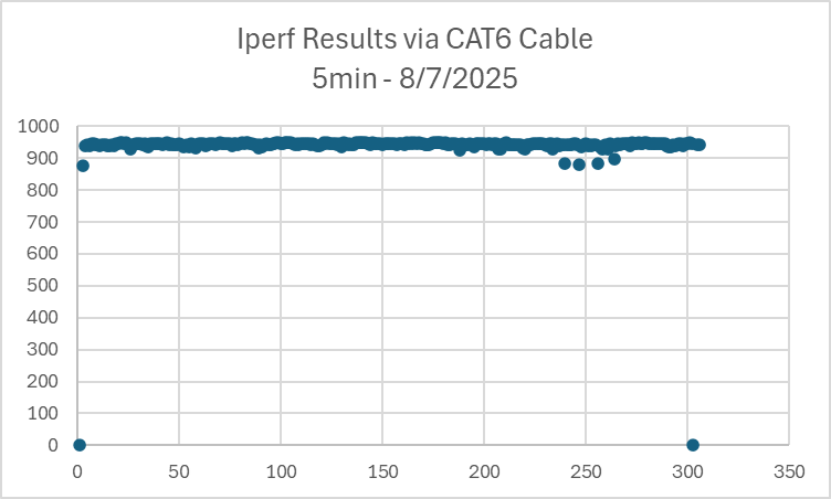
No slip rings at all – straight cable → should be a flat line at ~940 Mb/s.
-
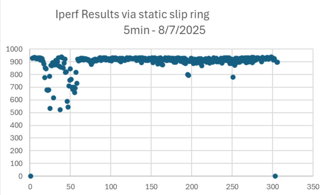
Single slip ring, stationary (Non GbE slipRing)
-
Single slip ring, moving (non GbE slipring)
-
Two slip rings in series, stationary (GbE slipring)
-
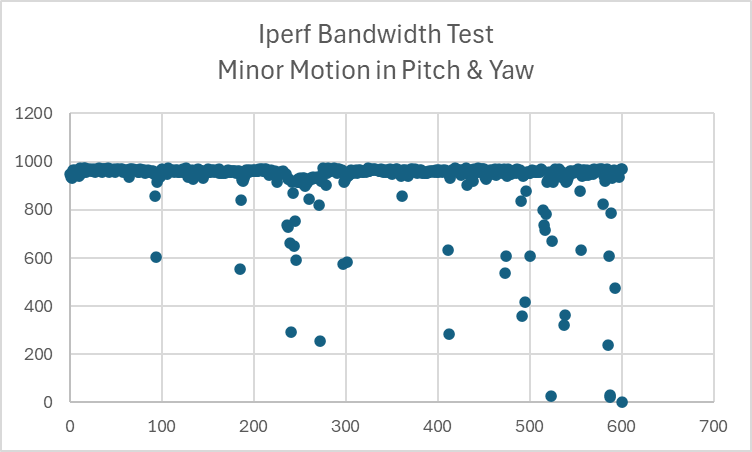
Two slip rings, moving (GbE Slipring)
Here is what we found during troubleshooting:
For our Iperf testing we used the following script on our test laptop (client) connected to another test laptop (server) via the SPE architecture.
”iperf3 -c xx.x.x.xxx -t 600 -R”
This yielded some momentary throughput slowdowns. (shown in original post)
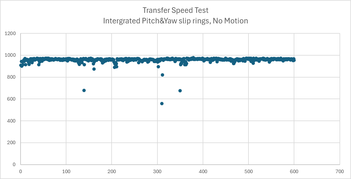
We updated our test to simulate a more realistic architecture, where we had a test laptop acting as an imager (client) connected over SPE to the processing module (Jetson Device – Server)
Using “iperf3 -c xx.x.x.xxx -t 600 -R” we saw stable results:
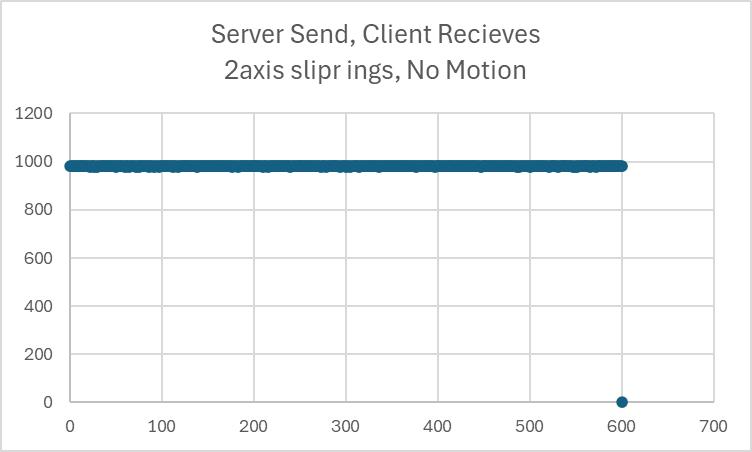
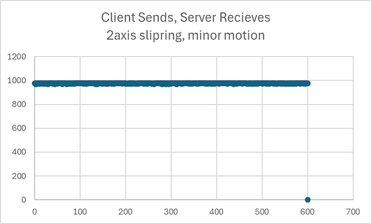
We also tested: ”iperf3 -c xx.x.x.xxx -t 600” which reverses data flow (Client Sends, Server Receives)
From all this testing, i think the root cause for throughput slowdowns is caused by network settings within one of the test laptops.
Transmitting data in the updated scheme seems to be more representative for our use case and removes one of the test laptops from the loop, which improved throughput.
We will keep Botblox updated as we add data to the sliprings and increase motor movement in both axes.
1 Like
Got it. Ultimately iperf3 can be limited by PC performance which would explain the issue. Glad we were able to find this issue. Keep us posted.